In a Circuit, there is a clock generating source either its PLL or a Clock Oscillator, or any other source. These Clock sources should maintain regular clock cycles with clean edges for the proper functioning of the Circuit. But, due to some issues for example Voltage Instability, Thermal Noise, Crosstalk, etc. the Clock Source is unable to produce a Clock with a proper Period and Clean Edge this phenomenon is known as Jitter. In short, “Jitter is defined as the failure of Clock Generating Source to produce a Clean Edge Clock Cycle”.
For example, a Clock Oscillator generates a Clock with 100 MHZ frequency so the clock period is 10ns means the consecutive edges will be 0ns 10ns 20ns 30ns, and so on for an ideal clock source. But, due to noise or issues, the clock will deviate from its ideal Period say its consecutive edges will be 0ns 9.9ns 20.9ns 29.9ns, and so on. In this example, there is a Jitter of +0.1ns and -0.1ns. Jitter is not desirable for the proper functioning of the circuit and should be taken care of.
Types of Clock Jitter
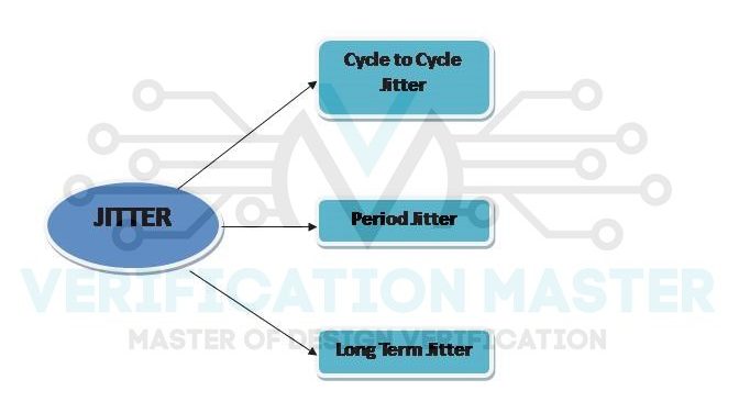
Cycle to Cycle Jitter
It is defined as the difference in periods of two consecutive clock cycles. For above example of 100 MHZ clock the consecutive cycles for Ideal Clock is 10ns 20ns 30ns 40ns . . . . 100ns . But, if Cycle to Cycle Jitter is present then the consecutive cycles will be 10ns 9.9ns 9.8ns, 9.7ns, 9.6ns . . . . . . 1.1ns 1ns it maintains a cycle to cycle jitter of 0.1ns.
Period Jitter
It is defined as the deviation of actual clock periods from Ideal Clock Periods. There are further two classifications of Period Jitter:
- Peak o Peak Jitter
For above example of 100MHZ clock the consecutive cycles for Ideal Clock is 10ns 20ns 30ns . . . 100ns. But actual clock is 10ns 9.9ns 9.8ns, 9.7ns. . . .1.1ns 1ns. So for this Peak to Peak period jitter is (10-10=0ns), (10-9.9=0.1ns) . . . . (10-1=9ns).
- RMS Jitter
Root Mean Square of all Peak to Peak Period Jitter.
Long Term Jitter
Long-term jitter is a variation of the clock after a long time from its ideal position. For the above example where the consecutive edges should be 0ns 10ns 20ns . . . . . for an ideal clock. But, if the 20th clock edge comes at 202ns then the long-term jitter is 2ns.
Different types of Jitter can be understood from the below waveform. Refer Fig.2

Fig. 2: Different type of Jitter
So, from this blog, you can answer the below set of questions
- Q1) Define Jitter.
- Q2) Mention types of Jitter.
- Q3) Explain types of Jitter.
- Q4) Give waveform to show different types of jitter