The Launch Edge and the Capture Edge are either Positive or Negative and it is known as Single Cycle-Path. But, there are scenarios when Data is Launched at Positive Edge and Captured at Negative Edge and vice versa such cases form a Half Cycle-Path. In other words, when Setup Checks occur at Half Cycle it is known as Half Cycle-Path.
Half Cycle Paths occur in the following cases:
- Data Launched from Positive Edge Triggered Flip-Flop and Captured at Negative Edge Triggered Flip-Flop. Refer Fig.1
- Data Launched from a Negative Edge Triggered Flip-Flop and Captured at Positive Edge Triggered Flip-Flop.
- Data Launched from Negative Level Sensitive Latch and Captured at Positive Level Sensitive Latch.
- Data Launched from Positive Level Sensitive Latch and Captured at Negative Level Sensitive Latch.
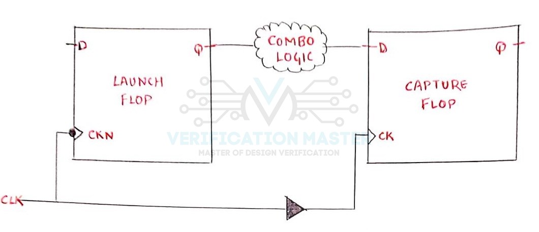
Fig. 1: Hald Cycle path
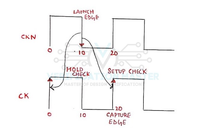
Fig. 2: Half Cycle Path Waveform
To get a clear understanding of Half Cycle Path let consider the above Fig. 1 and Fig. 2 in which Data is Launched at Negative Edge from Launch Flop and Captured at Positive Edge at Capture Flop. Let us take Time-Period 20ns in which Falling Edge is at 10ns and Rising Edge is at 20ns. Since it is a Half Cycle Path so Data Launched at 10ns should be Captured at 20ns. Thus, Data gets 10ns to travel from Launch Flop to Capture Flop instead of 20ns. This makes the Setup Check tighter. Since, Hold Check takes place one cycle before Capture Edge, Hold Check takes place at 0ns. It gives a complete Half Cycle Margin to the Hold Check and thus makes Hold Slack more Positive.
- In case of Half Cycle Path the Setup equation modifies to :
Tck-q + Tpd < T(period/2) – Tsetup + Tskew
Where, Tck-q is the delay between clock pin to q, Tpd is the propagation delay of combinational logic, Tperiod/2 is the half cycle time period, Tsetup setup time of the capture flop and Tskew is the skew between launch and capture flop.
- Uncertainty in the relative positive and negative edges results in the duty cycle variation of the clock source. So, in half cycle path Duty Cycle of the clock source varies. Also, we can say that duty cycle variation is the uncertainty in the arrival of negative edge after positive edge has arrived at a given point of time. For example, if we have a clock with 50% duty cycle with 20ns period and +/- 10% duty cycle variation. So, if the positive edge of the clock is at 20ns the negative clock edge is expected to occur at 28ns or 32 ns. So, the equation for setup check is modified as:
Tck-q + Tpd < (T(period/2) -Tsdc) – Tsetup + Tskew
Where, Tsdc is Clock Source Duty Cycle Variation.
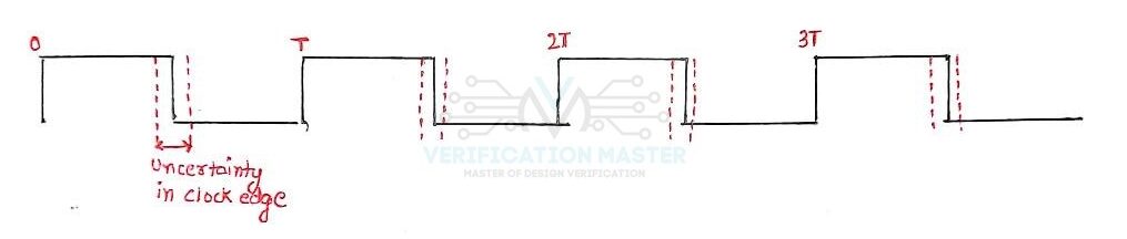
Fig. 3: Uncertainity in Clock Edge
So from this blog, you can answer the below set of Questions:
- What is a Half-Cycle Path?
- Explain Setup Check and Hold Check in Half-Cycle Path with waveform.
- What is the modified Setup Equation for Half-Cycle Path?
- How Duty-Cycle Variation Affects the Setup Equation in Half-Cycle Path?