We have studied lots of things related to Verilog, so let’s learn to design something new through Verilog.
A flip-flop or latch is a bistable multivibrator that has two stable states and may be used to store state information. Signals provided to one or more control inputs can cause the circuit to change state, and it will have one or two outputs.
In sequential logic, it is the fundamental storage element. Flip-flops and latches are key components of digital electronics systems used in computers, communications, and a variety of other applications.
Let’s start with some of the basic flipflops.
JK Flipflops
The most adaptable of the basic flip flops is the JK flip flop. In clocked sequential logic circuits, a JK flip-flop is used to store one bit of data.
It performs virtually identically to an SR flip flop. The sole difference is that the undefined condition when both S and R are 1 is no longer present.

Fig 1: JK Flipflop
A JK flip-flop has four potential input combinations because of this extra timed input: “logic 1”, “logic 0”, “no change”, and “toggle”.
We will construct a testbench for JK Flip Flop and programme it in Verilog.
module jk_ff ( input j, input k, input clk, output q);  //input output port

   reg q;

   always @ (posedge clk)  //active low ansynchronous reset
      case ({j,k})
         2'b00 :  q <= q;
         2'b01 :  q <= 0;
         2'b10 :  q <= 1;
         2'b11 :  q <= ~q;
      endcase
endmodule
Testbench:
module tb_jk;
   reg j;
   reg k;
   reg clk;

   always #5 clk = ~clk;  //generate clock

   jk_ff    jk0 ( .j(j),
                  .k(k),
                  .clk(clk),
                  .q(q));

   initial begin  //testcase
      j <= 0;
      k <= 0;

      #5 j <= 0;
         k <= 1;
      #20 j <= 1;
          k <= 0;
      #20 j <= 1;
          k <= 1;
      #20 $finish;
   end

   initial
      $monitor ("j=%0d k=%0d q=%0d", j, k, q);
endmodule
The waveform of the above example is shown below.
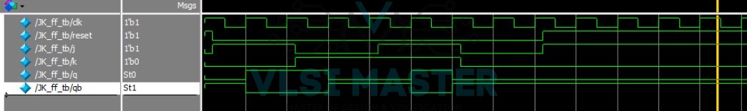
Fig 2 JK Flipflop waveform
D flipflop
A D flip-flop is a sequential element that follows the input pin d at the specified edge of the clock. The D flip-flop is a key component in digital logic circuits.
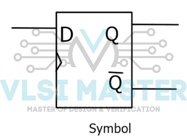
Fig 2: D flipflop
When an active edge transition occurs on its clock input, a D flip flop transfers the value of a signal on its D input to its Q output. The output value is then retained until the next active clock cycle.
We will construct a testbench for D Flip Flop and programme it in Verilog.
module dff (input d,
              input rstn,
              input clk,
              output reg q);

    always @ (posedge clk or negedge rstn)  // active low asynchronous reset
       if (!rstn)
          q <= 0;
       else
          q <= d;
endmodule
module tb_dff;
    reg clk;
    reg d;
    reg rstn;
    reg [2:0] delay;

    dff  dff0 ( .d(d),
                .rsnt (rstn),
                .clk (clk),
                .q (q));

    always #10 clk = ~clk;  // generate clock
    initial begin  		// testcase
        clk <= 0;
        d <= 0;
        rstn <= 0;

        #15 d <= 1;
        #10 rstn <= 1;
        for (int i = 0; i < 5; i=i+1) begin
            delay = $random;
            #(delay) d <= i;
        end
    end
endmodule
The waveform of the above example is shown below.
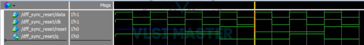
Fig 4 D Flipflop waveform
T Flipflop
To avoid an intermediate state in an SR flip-flop, T stands for (“toggle”) flip-flop.
To avoid an intermediate state, we should only offer one input to the flip-flop named Trigger input Toggle input.
The flip flop then functions as a toggle switch. The complement of the current state output is used to modify the following output state. Toggling is the name given to this process.
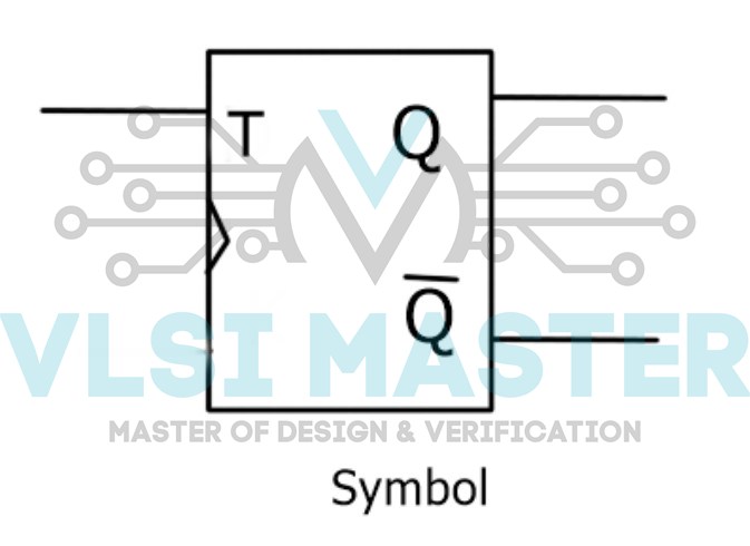
Fig 3: T flipflops
We can build the T flip-flop by modifying the JK flip-flop. The T flip-flop has only one input, which is formed by joining the JK flip-input. Flipflop’s T is the name given to this particular input.
The T flip-flop block diagram is shown below, where T denotes the “toggle” input and CLK denotes the “clock signal” input.
module tff ( input clk, input rstn, input t, output reg q);  //input ouptut port

  always @ (posedge clk) begin  // active low asynchronous reset

    if (!rstn)
      q <= 0;
    else
        if (t)
            q <= ~q;
        else
            q <= q;
  end
endmodule
module tb;  //testbench
  reg clk;
  reg rstn;
  reg t;

  tff u0 (  .clk(clk),
            .rstn(rstn),
            .t(t),
          .q(q));

  always #5 clk = ~clk;  //generate clock

  initial begin  //testcase
    {rstn, clk, t} <= 0;

    $monitor ("T=%0t rstn=%0b t=%0d q=%0d", $time, rstn, t, q);
    repeat(2) @(posedge clk);
    rstn <= 1;

    for (integer i = 0; i < 20; i = i+1) begin
      reg [4:0] dly = $random;
      #(dly) t <= $random;
    end
    #20 $finish;
  end
endmodule
The waveform of the above example is shown below.
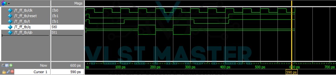
Fig 6 T Flipflop waveform
Counter
A counter is a specific form of sequential circuit used to count the pulse. Alternatively, it is a collection of flip flops to which the clock signal is applied.
The counter is one of the flip flop’s most common applications. The counter’s output comprises a predetermined state based on the clock pulse.
The counter’s output may be used to count the number of pulses.
So let’s discuss the most common type of counter that is a ripple counter.
Ripple Counter
A ripple counter is an asynchronous counter in which the output of the preceding flop clocks all flops except the first.
Asynchronous indicates that the circuit elements do not share a common clock. A four-bit counter, for example, will count from 0000 to 1111.
Design
The first T Flip Flop will get a 1 kHz clock signal, and the next three Flip Flops will receive their clocks from the preceding Flip Flop’s output (Q). See the diagram below:
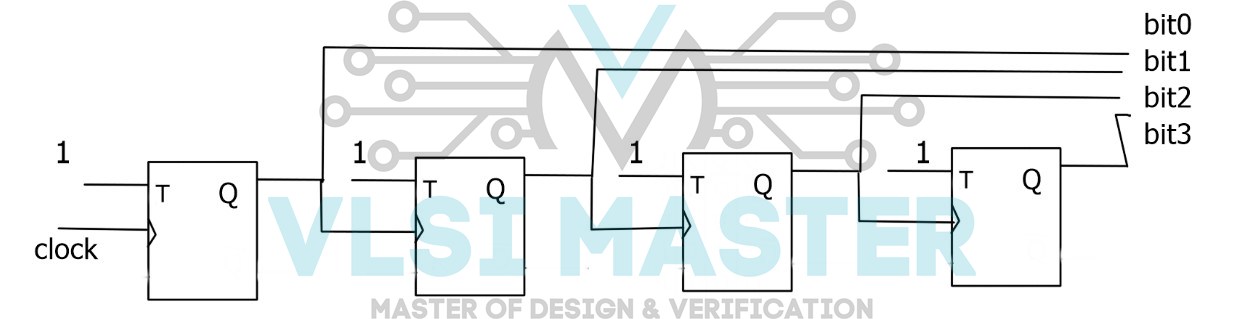
Fig 7: Ripple Counter
Because we require a four-bit ripple counter, the above circuit has four T-Flips. First T flipflop clock is supplied by a 1Khz digital source, while the remainder of the Flip Flops use the prior Flip Flop output as the clock.
T Flip Flop toggles input on every clock edge since every T flip flops’ input T is HIGH (1).
module tff (input clk, input rstn, input t, output reg q);
always@ (posedge clk) begin
if (!rstn)
q <= 0;
else
if (t)
q <= ~q;
else
q <= q;
end
endmodule


module tb;
reg clk;
reg rstn;
reg t;
tff u0  (.clk (clk), .rstn(rstn), .t(t), .q(q) ) ;
always #5 clk = ~clk;
initial begin
{rstn, clk, t} <= 0;

        $monitor (“ T=%0t rstn=%0b t=%0d q=%0d”,  $time, rstn, t, q);
repeat (2) @(posedge clk);
rstn <= 1;

for (integer i = 0; i < 20 ; i = i + 1 ) begin
reg [4:0] dly = $random;
 # (dly)  t < = $random;

end
#20 $finish;
end
endmodule
Hence, from this blog, we studied what a flipflop is and how to design some of the flip flops. We also learn to design the counter from flipflops.
- What is the function of the JK flipflop?
- What is the function of the D-flipflop?
- What is the function of a flip-flop?
- How to design a 4 bit ripple counter from a flip flop?